

Skip to content
PartsPlan AIPartsPlan AI

Component checks for AI-assisted circuit design

Tested with the same AI:
more accurate than attaching the PDF directly.

Your AI picks the parts. PartsPlan hands it the evidence for each value, with the page in the manufacturer's original.

Free $0 · 300 tool calls a month · no card needed · Personal $19/month plus applicable sales tax / VAT · Companies & organizations: by agreement — See pricing

PartsPlan is a hosted developer API (MCP server). Subscriptions pay for API usage. We are not a marketplace and don't sell parts or documents.

We don't hand your AI a PDF. We hand it evidence, already organized.

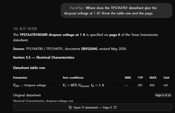
A real ChatGPT session using PartsPlan · recorded October 2026
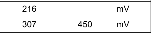
ChatGPT conversation. The answer shows the dropout-voltage row (1 A, TYP 307 mV, MAX 450 mV) from the electrical characteristics table on page 6 of the TPS7A4701 datasheet, with a button that opens page 6 of the original.
Datasheet original we checked it against · Texas Instruments · TPS7A4700/TPS7A4701 (SBVS204G) · page 6Dropout voltage V(DO)

⋯ Rows in between omitted ⋯

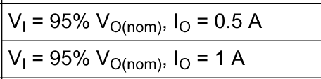
Header row and the two dropout-voltage rows (0.5 A 216 mV; 1 A 307 mV, max 450 mV) of the electrical characteristics table on page 6 of the TPS7A4701 datasheet

Row the answer cited · highlighted by us

Rows in between and the MIN column are omitted. Enlarge to see all of page 6.

Datasheet original we checked it against

Texas Instruments · TPS7A4700/TPS7A4701 (SBVS204G) · page 6

Open the manufacturer's original ↗

Q: Where is the TPS7A4701 dropout voltage at 1 A? → A: page 6 table, TYP 307 mV · MAX 450 mV

Small tests with the same AI

30 values that exist only in graphs →

Conduction voltage, switching losses and diode voltage of a power IGBT (IKW40N120CS6) — printed only in graphs, not in tables

30 / 30

PartsPlan connected · all 6 runs

25 / 30

PDF attached directly · 1 run

Same AI · one part (16 pages) · within 3% or 0.05 V counts as correct · September 2026
12 hard questions, run again →

4 deep-table, 5 graph and 3 package-drawing questions — each with a similar wrong value right next to the answer

12 / 12

PartsPlan connected · all 4 runs

10–11 / 12

PDF attached directly · 3 runs: 10, 11, 10

Same AI · tables, graphs and drawings · September 2026

The same work, faster →

Drawing a KiCad footprint and routing a 2-layer board — same AI, same task

10.1 min

Footprints · PartsPlan connected

24.8 min

Without PartsPlan

10.6 min

PCB routing · PartsPlan connected

21.3 min

Without PartsPlan

3-run averages · compared with no PartsPlan (web, shell and KiCad) · routing quality score: both 20 out of 20 (final run) · October 2026

See the 12 questions and answers
  1. Table · STM32F103C8T6 — max Run-mode current with code running from RAM (36 MHz, peripherals on) at 105 °C: 25.5 mA (p. 41) · trap: 28.7 mA in the Flash table just above
  2. Table · STM32F103C8T6 — ΘJA of the package its ordering code implies (T = LQFP48): 55 °C/W (p. 101) · trap: 32 °C/W for the other 48-pin package, UFQFPN48
  3. Table · STM32F103C8T6 — max Stop-mode current (regulator in low-power mode) at 105 °C: 340 µA (p. 44) · trap: 370 µA in the next row (regulator in Run mode)
  4. Table · STM32F103C8T6 — max external source impedance RAIN at fADC 14 MHz with 13.5 sampling cycles: 11.4 kΩ (p. 75) · trap: the general 50 kΩ on the previous page
  5. Graph · LM358DR — typical output source current limit at 70 °C: 29.4 mA (p. 23) · trap: 38.6 mA from the LM358B curve in the same document
  6. Graph · AP2112K-3.3 — dropout at 400 mA and 85 °C: 200 mV (p. 15) · trap: 171 mV on the neighbouring 25 °C curve
  7. Graph · BSS138 — RDS(on) at VGS 3.3 V, ID 110 mA and 125 °C: 1.95 Ω (p. 4) · trap: 1.19 Ω on the 25 °C curve
  8. Graph · BSS138 — body-diode VSD at IS 10 mA and 25 °C: 0.646 V (p. 4) · trap: 0.47 V on the 125 °C curve
  9. Graph · BSS138 — drain current at VDS 10 V, VGS 1.75 V and 125 °C: 0.117 A (p. 4) · trap: 0.076 A on the 25 °C curve
  10. Drawing · STM32F103C8T6 — max LQFP48 lead width b: 0.27 mm (p. 99) · trap: 0.23 mm for b1 in the next row
  11. Drawing · SS34 — max lead width in the top view: 3.27 mm (p. 4) · trap: the 3.39 mm land-pattern pad right beside it
  12. Drawing · AP2112K-3.3 — EN pin and pin 4: EN is pin 3; pin 4 is NC on the fixed-output version (p. 2) · trap: EN = pin 5 in the SOIC-8 column

Not perfect: in the 12-question test with a small AI model, PartsPlan gave 3 wrong values and the attached PDF 5. Conditions and full results →

  • Whose document it is, first

    We check the company and part number printed on the document, so it is the maker's document for the part you asked about.

  • A page number for every value

    Values from tables, graphs and drawings come with the document and page, plus the original page image to check against.

  • Hard-to-read documents too

    Values inside graphs are read out as numbers, and scanned documents and Chinese-language datasheets have already been read.

  • Organized in advance, so faster

    Prepared documents are found and read from the first question. In the footprint and routing tests, the three-run average time was half or less.

14M+Datasheet pages

7.2M+Part numbers

Connects to the AI you already use

  1. Pick your AI below

  2. Sign in when the connect window opens (first time: free sign-up)

    Claude, ChatGPT, Cursor and VS Code open the PartsPlan sign-in window when you connect; first-timers can sign up for free right there (no card). Codex and Gemini CLI get a key from the setup guide.

  3. Ask about parts as you normally would

    What is the TPS7A4701 dropout voltage at 1 A? Give me the datasheet page.
    More examples
    Check every line of this BOM for the manufacturer's datasheet and tell me which pages to open first.
    What does the TPS563200 current-vs-ambient curve give at 85 °C?
    Put AO3400A, 2N7002 and BSS138 in one table — VDS, ID, VGS(th), RDS(on), Qg — with the page and condition for each cell.

What the AI built with PartsPlan

We gave the same AI the same tasks. These are what the side with PartsPlan connected actually produced.

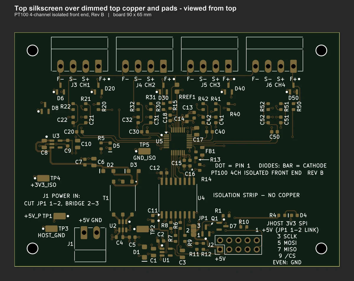
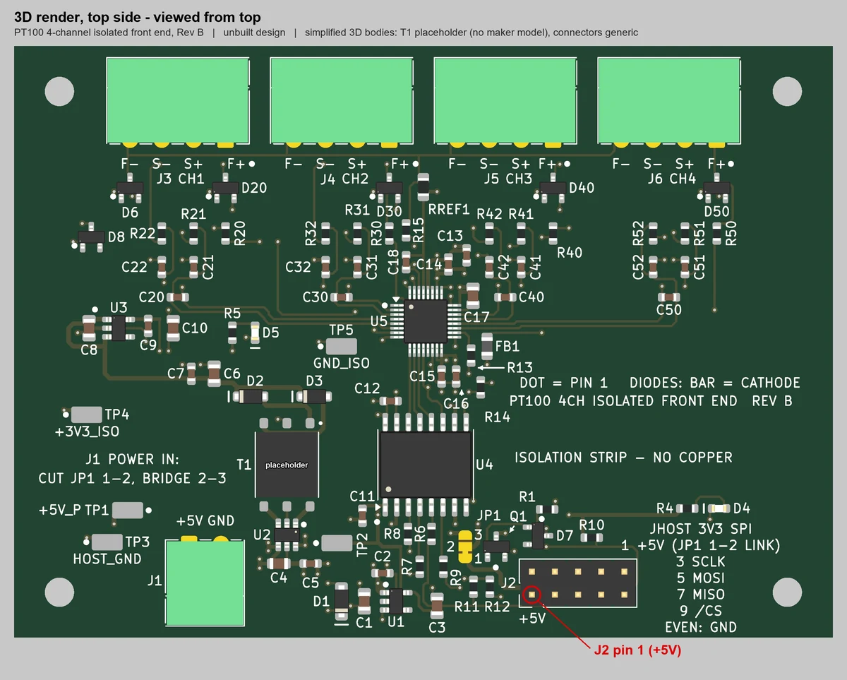
KiCad 3D top view of the AI-designed 4-channel isolated PT100 board — four sensor terminals, ADC, isolator and transformer

Designed by AI end to end

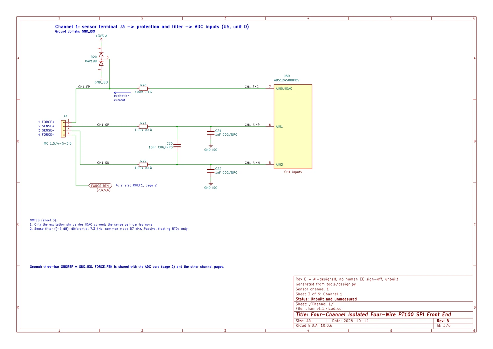
4-channel isolated PT100 measurement board — from requirements to fabrication files by AI

AI agents produced the schematic, placement, routing, BOM, checks and documents; no human edited the schematic or the copper

  • 4 layers, 90 × 65 mm · 88 parts · ADS124S08 24-bit ADC
  • ERC 0 · DRC 0 violations · 0 unconnected (an independent re-run agrees)
  • Every datasheet value cited by document and page — evidence from PartsPlan
  • No human edited the schematic or the copper · no human EE review

Unbuilt and unmeasured design (calculated values) · October 2026

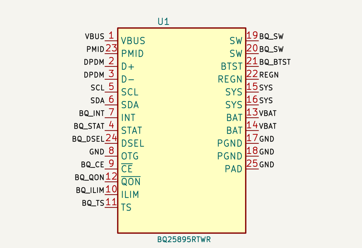
The BQ25895 charger IC section of the AI-made schematic — net labels such as VBUS, SDA, SW and BAT on all 25 pins.

Circuit design

Charger IC schematic

Part of the schematic the AI made in the test · every pin connected by a net label

Major errors

0

PartsPlan connected

3

Without PartsPlan

Same AI · same task · 90-minute cap · one run per side · the other side also used web, shell and KiCad · October 2026

Download KiCad files(124 KB · ZIP)

Test output example — review before building

See the use cases →
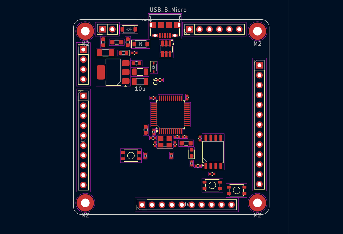
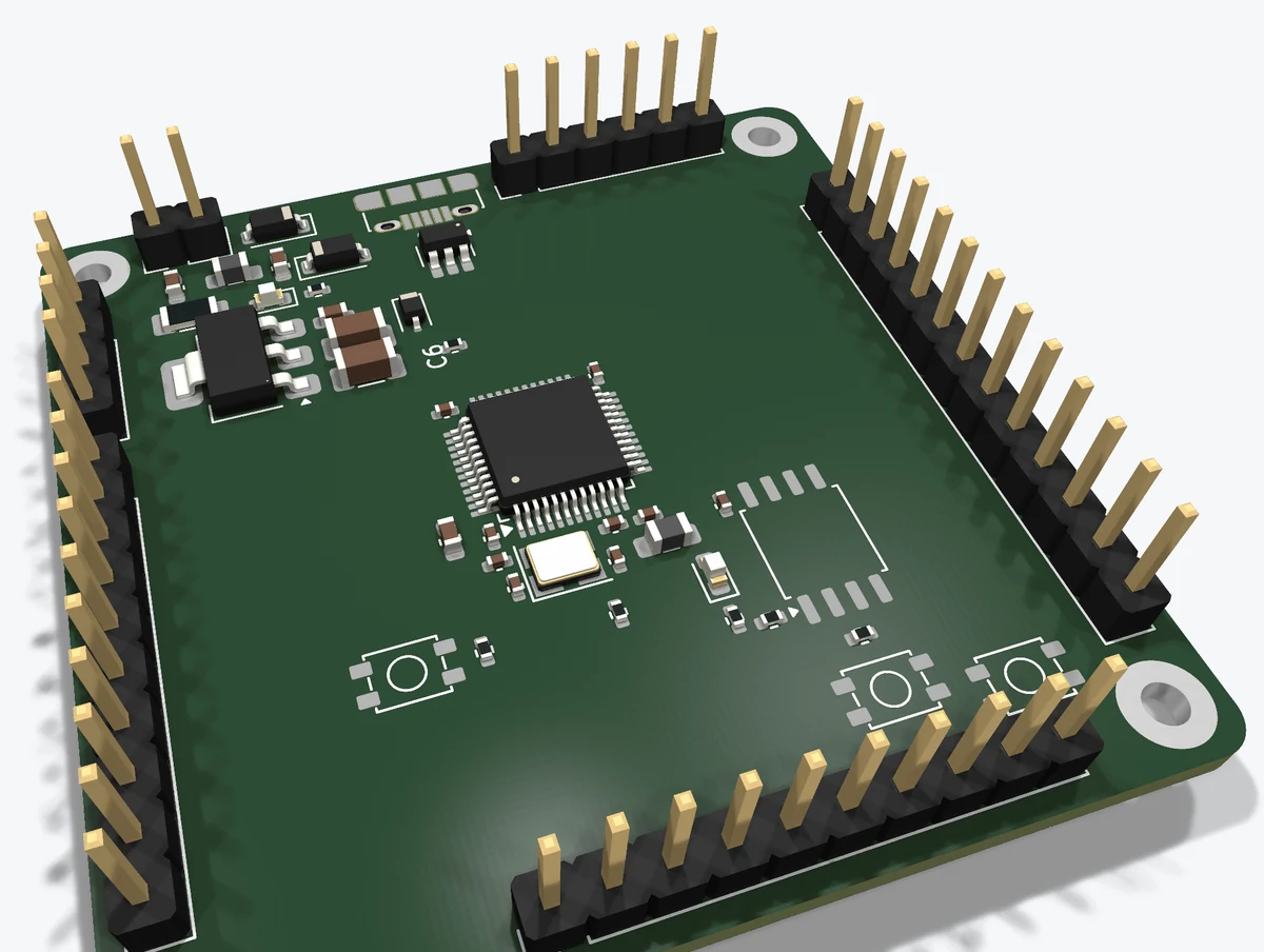
The STM32 development board with all 49 parts placed by the AI, drawn in the KiCad PCB editor — pads, part outlines and silkscreen

PCB placement

49-part STM32 board placement

The board the AI placed in the test (KiCad 2D and 3D) · run 2 of 3

Average score (of 100, three-run average)

92.6

PartsPlan connected

81.7

Without PartsPlan

Same AI · three runs per side, ahead in all three · the other side also used a shell and KiCad · October 2026

See the use cases →
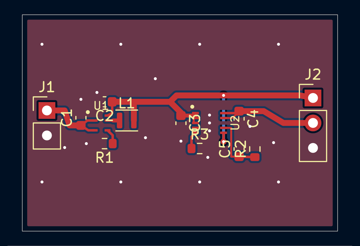
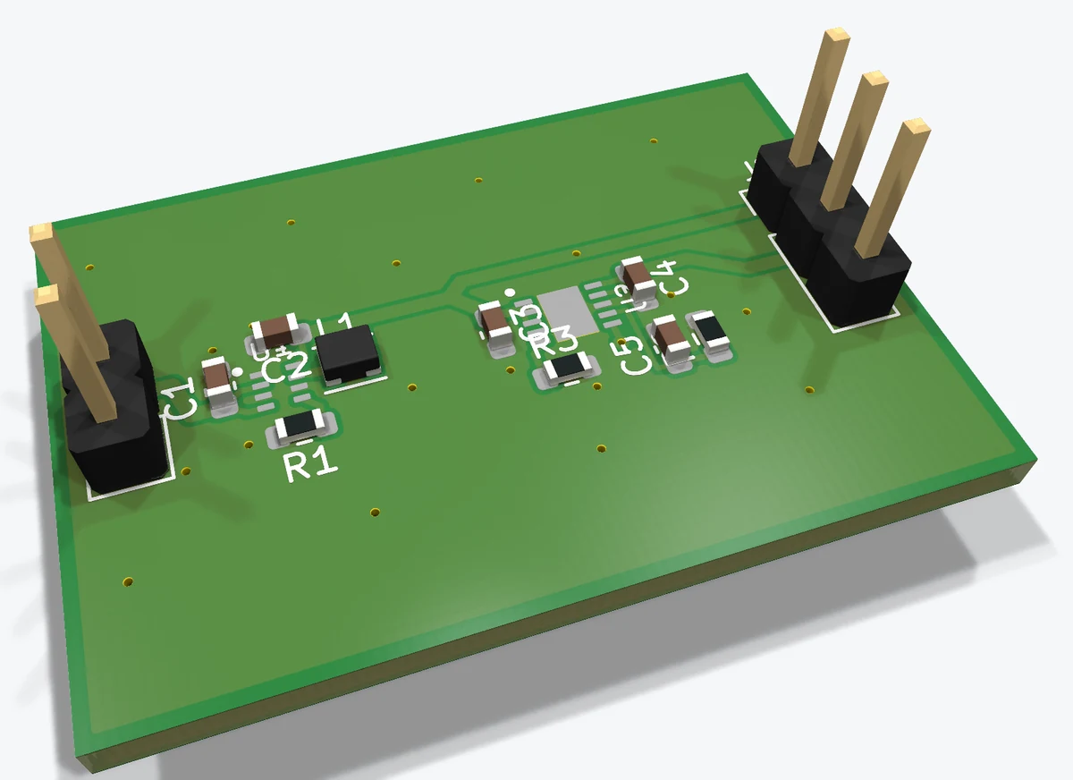
The two-layer board routed by the AI, drawn in the KiCad PCB editor — red front and blue back copper traces, ground pour and reference designators

PCB routing

Buck and LDO two-layer board

The board the AI routed in the test (KiCad 2D and 3D) · run 2 of 3 (20/20)

Average time (three-run average)

10.6 min

PartsPlan connected

21.3 min

Without PartsPlan

Same quality score: both scored 20 out of 20 (final run)

same AI · the other side also used a shell and KiCad · October 2026

Download KiCad files(31 KB · ZIP)

Test output example — review before building

See the use cases →
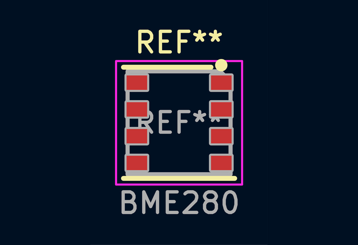
The BME280 footprint the AI made, shown in the KiCad footprint editor — eight pads, silkscreen outline and courtyard

Footprints

BME280 footprint

The footprint the AI made in the test, in the KiCad footprint editor · run 1 of 3

Average time (three-run average)

10.1 min

PartsPlan connected

24.8 min

Without PartsPlan

Six parts · same AI · three runs per side · the other side also used a shell and KiCad · October 2026

Download KiCad files(12 KB · ZIP)

Test output example — review before building

See the use cases →
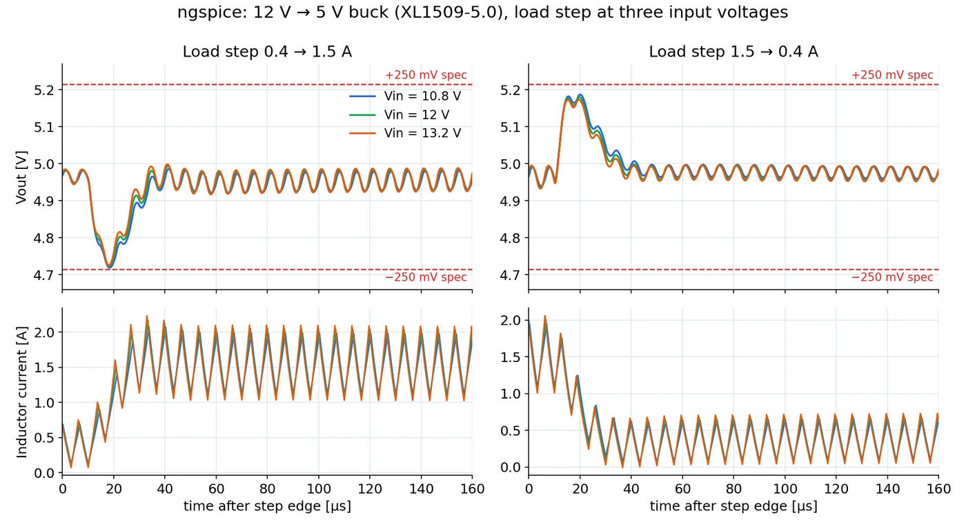
Circuit simulation — 12 V→5 V buck load stepTime from schematic to simulation to PCB (first comparison, one run): 64 min vs 85 min
ngspice load-step response of a 12 V to 5 V buck (XL1509-5.0) at 10.8, 12 and 13.2 V input — output voltage and inductor current against ±250 mV limit lines

Circuit simulation

12 V→5 V buck load step

An ngspice model the AI built from manufacturer datasheet values · values missing from the documents were stated as assumptions · shown: the re-run

Time from schematic to simulation to PCB (first comparison, one run)

64 min

PartsPlan connected

85 min

Without PartsPlan

Lesser-known Chinese and Taiwanese parts · all seven documents from the manufacturers · design quality on par · same AI · one run each · October 2026

With the EDA tools you use

  • In the tests the AI produced schematics, boards and footprints in KiCad format, and those files open as they are in KiCad 10 (the images above are those files and placements drawn by KiCad).
  • Package drawings and land patterns come exactly as printed, so whichever tool you draw in — EasyEDA, Altium or others — the evidence is the same original page.
Draw in EasyEDA, build with JLCPCBThe BOM exported from EasyEDA, as is — the maker's document found for 14 of 14 real lines (October 2026, one run)

Pass on the BOM exactly as EasyEDA exports it — design, datasheet checks and assembly ordering stay on the same part numbers.

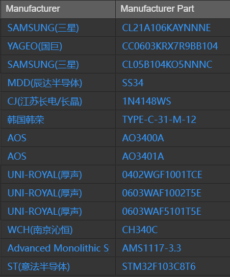
  1. Design in EasyEDADraw the circuit and export the BOM. The manufacturer column (for example MDD(辰达半导体)) comes out together with C numbers.
  2. Check with AI + PartsPlanPass the BOM on as it is, and each line gets that maker's document — 14 of 14 lines of an actually exported BOM (October 2026, one run).
  3. Order assembly at JLCPCBThe C numbers in an EasyEDA BOM are the same as JLCPCB assembly part numbers, so the checked part numbers go into the order as they are.
  • Hand the AI the BOM exactly as EasyEDA exports it, and each line, passives included, is checked against that manufacturer's original datasheet — in a comparison test with the same AI (Claude) and a 14-line BOM in EasyEDA's format, lines confirmed from the manufacturer's original: web only 8, web + PartsPlan 14 (October 2026, one run).
  • Each line comes back with the manufacturer's document and the pages to open first (pinout, package, electrical characteristics), and the AI opens those pages to review them.
  • In a test with a BOM actually exported from EasyEDA Pro and passed on unedited — 14 lines, maker names as the export writes them (for example 'MDD(辰达半导体)', with the Chinese name alongside) and C numbers included — that maker's document was found for all 14 lines (October 2026, one run).
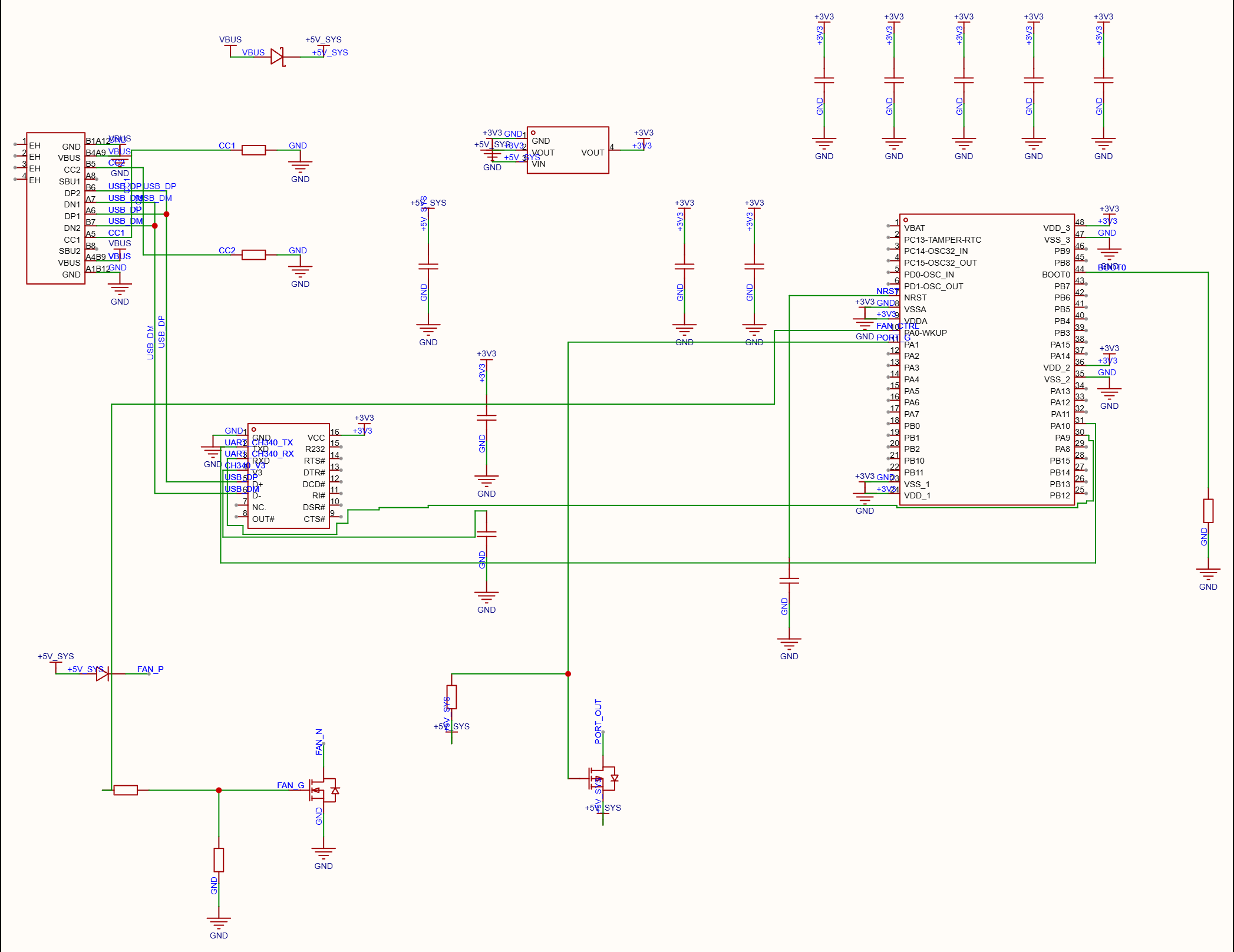
EasyEDA Pro schematic: USB-C connector, CH340C USB-to-serial, STM32F103 microcontroller, AMS1117-3.3 regulator, two fan/port MOSFETs and passives
A comparison-test circuit made in EasyEDA Pro (25 parts). The 14-line BOM exported from this circuit was passed on unedited.

EasyEDA Pro test circuit — USB data logger

A comparison-test circuit made in EasyEDA Pro (25 parts). The 14-line BOM exported from this circuit was passed on unedited.

EasyEDA Pro property list, 14 rows — manufacturer column: SAMSUNG(三星), YAGEO(国巨), MDD(辰达半导体), CJ(江苏长电/长晶), 韩国韩荣, AOS, UNI-ROYAL(厚声), WCH(南京沁恒), Advanced Monolithic S…, ST(意法半导体) · manufacturer part column: CL21A106KAYNNNE through STM32F103C8T6
Captured directly in EasyEDA Pro: the test circuit's property list (the same parts as the 14-line BOM), with the manufacturer column exactly as EasyEDA writes it.
The originals your AI readsCharacteristic curves, circuits and waveforms, package drawings — the manufacturer's original, with page numbers

Tables, graphs, circuits and package drawings exactly as the manufacturer printed them, with document and page number.

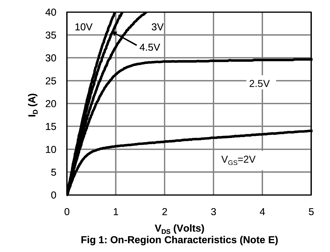
AO3400A datasheet page 3, Fig 1 — drain current versus drain-source voltage for gate voltages from 2 V to 10 V
Characteristic curvesMOSFET output characteristicsAlpha & Omega · AO3400A · page 3 · Fig 1

MOSFET output characteristics

Alpha & Omega · AO3400A · page 3 · Fig 1

Open the manufacturer's original ↗
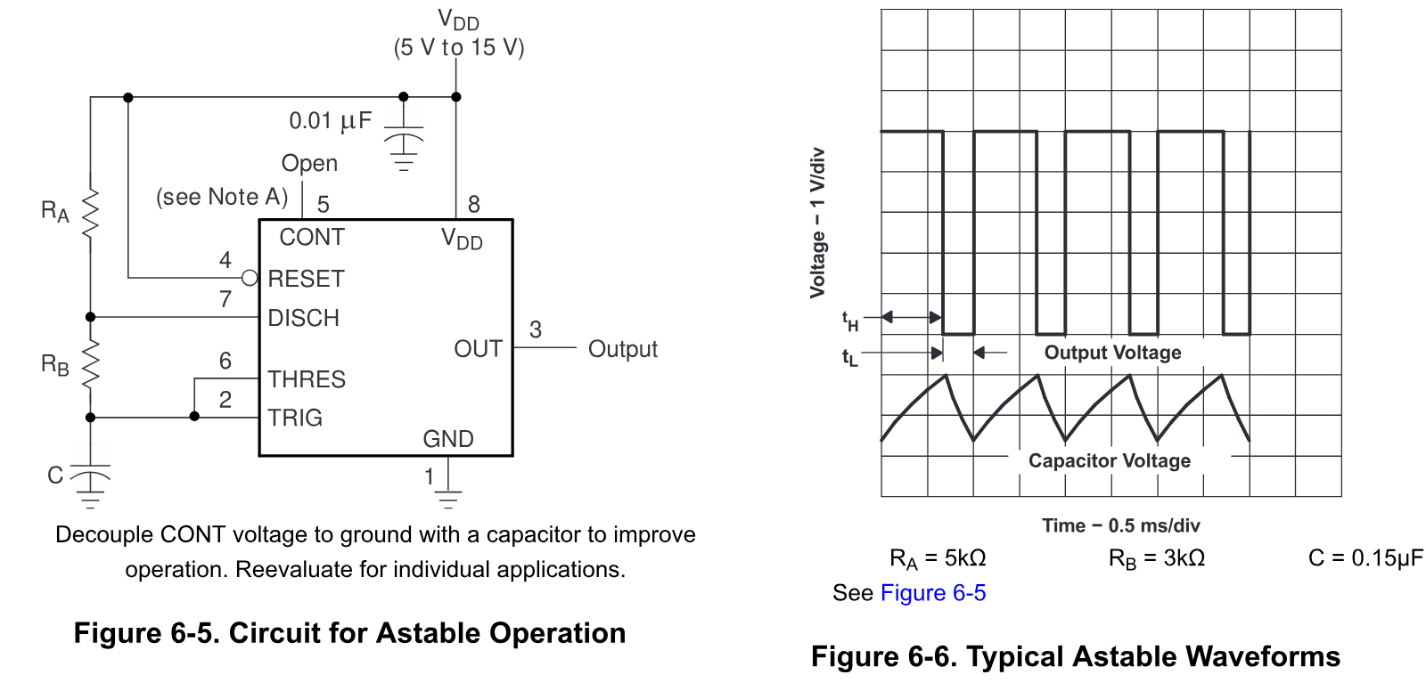
TLC555 datasheet page 15 — astable operation circuit (Figure 6-5) and output and capacitor voltage waveforms (Figure 6-6)
Circuit and waveforms555 astable circuit and waveformsTexas Instruments · TLC555 · page 15 · Figures 6-5, 6-6

555 astable circuit and waveforms

Texas Instruments · TLC555 · page 15 · Figures 6-5, 6-6

Open the manufacturer's original ↗
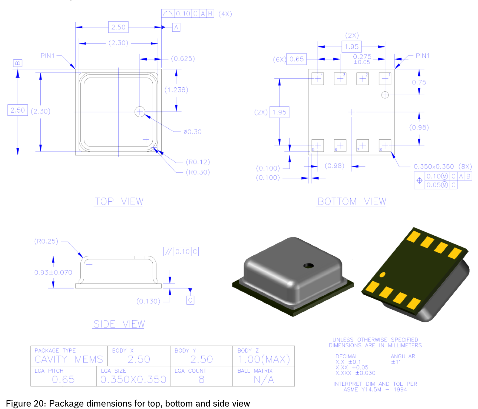
BME280 datasheet page 42, Figure 20 — top, bottom and side view package dimensions (2.50 × 2.50 mm, 8-pin LGA)
Package drawingPackage dimensionsBosch Sensortec · BME280 · page 42 · Figure 20

Package dimensions

Bosch Sensortec · BME280 · page 42 · Figure 20

Open the manufacturer's original ↗

Try it on the parts you use

Start on the free plan and change plans whenever you need to.