
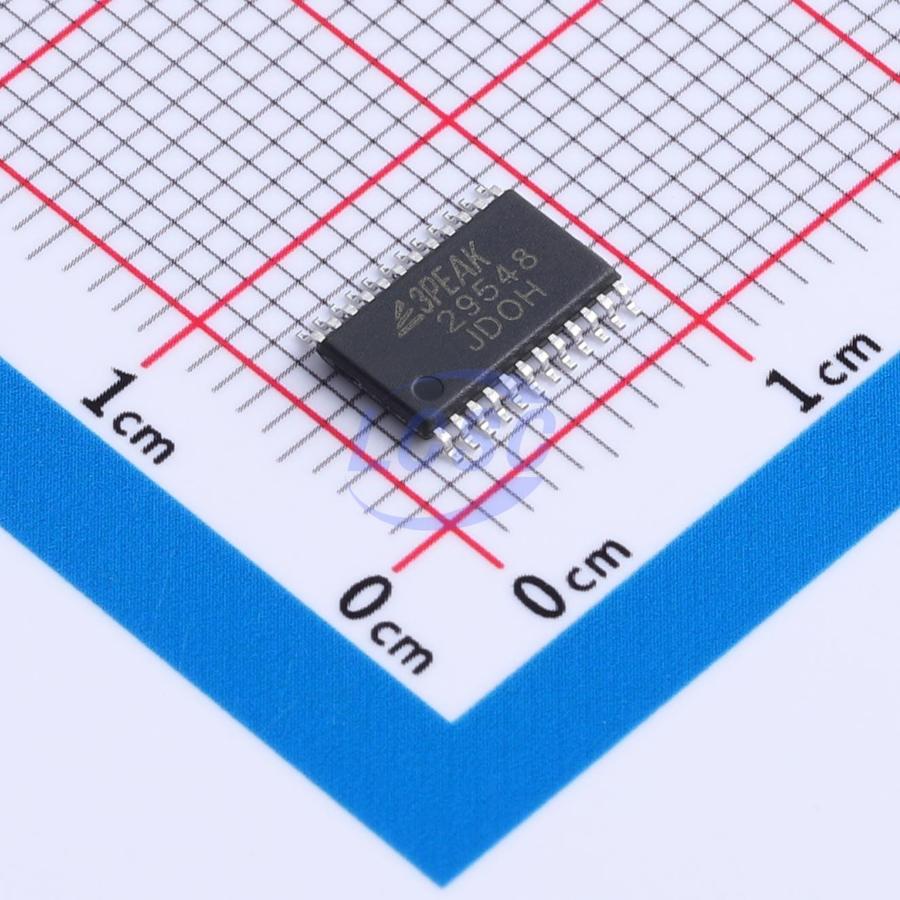
No Domestic Stock
Request a quote for this part and sellers will provide prices.
Key Specs Summary(10)
Datasheet cross-check2 enriched1 corrected
- Data RateEnriched
- 400kHz
- features
- Reset function;IO level configurable;Cascade and address expansion
- interface
- I2C
- Number Of ChannelsEnriched
- 8
- Number Of I O
- 16
- Number Of Supporting Devices
- 8
- Operating Temperature
- -40℃~+85℃
- packageCorrected
- TSSOP24
- Quiescent Supply Current
- 1.8uA
- Voltage Supply
- 2.3 to 5.5V
Datasheet Extracted
Facts extracted directly from the datasheet (sourced)Pin Configuration · TSSOP24 · 24 pins
| # | Name | Type | Function |
|---|---|---|---|
| 1 | A0 | input | Address input 0. Connect directly to VCC or ground. |
| 2 | A1 | input | Address input 1. Connect directly to VCC or ground. |
| 3 | RESET | input | Reset input, active LOW. Connect to VCC or pull up the power of the master side through a pull-up resistor, if not used. |
| 4 | SD0 | bidirectional | Data 0. Connect to the power of slave channel 0 through a pull-up resistor. |
| 5 | SC0 | bidirectional | Clock 0. Connect to the power of slave channel 0 through a pull-up resistor. |
| 6 | SD1 | bidirectional | Data 1. Connect to the power of slave channel 1 through a pull-up resistor. |
| 7 | SC1 | bidirectional | Clock 1. Connect to the power of slave channel 1 through a pull-up resistor. |
| 8 | SD2 | bidirectional | Data 2. Connect to the power of slave channel 2 through a pull-up resistor. |
| 9 | SC2 | bidirectional | Clock 2. Connect to the power of slave channel 2 through a pull-up resistor. |
| 10 | SD3 | bidirectional | Data 3. Connect to the power of slave channel 3 through a pull-up resistor. |
| 11 | SD4 | bidirectional | Data 4. Connect to the power of slave channel 4 through a pull-up resistor. |
| 12 | SC4 | bidirectional | Clock 4. Connect to the power of slave channel 4 through a pull-up resistor. |
| 13 | SD5 | bidirectional | Data 5. Connect to the power of slave channel 5 through a pull-up resistor. |
| 14 | SC5 | bidirectional | Clock 5. Connect to the power of slave channel 5 through a pull-up resistor. |
| 15 | SD6 | bidirectional | Data 6. Connect to the power of slave channel 6 through a pull-up resistor. |
| 16 | SC6 | bidirectional | Clock 6. Connect to the power of slave channel 6 through a pull-up resistor. |
| 17 | SD7 | bidirectional | Data 7. Connect to the power of slave channel 7 through a pull-up resistor. |
| 18 | SC7 | bidirectional | Clock 7. Connect to the power of slave channel 7 through a pull-up resistor. |
| 19 | A2 | input | Address input 2. Connect directly to VCC or ground. |
| 20 | SCL | bidirectional | I2C Clock |
| 21 | SDA | bidirectional | I2C Data |
| 22 | GND | power in | Ground |
| 23 | VCC | power in | Supply Voltage |
| 24 | A0 | input | Address input 0. Connect directly to VCC or ground. |
Source 1 ↗Extraction confidence: High
Package Info
- msl
- 3
- package
- TSSOP24
Absolute Maximum Ratings
| Supply Voltage | 7V | |
| Input Voltage | 7V | |
| Input Clamp Current | 20mA | VI < 0 |
| Output Clamp Current | 25mA | VO < 0 |
| Continuous Current through GND | 100mA | |
| Maximum Junction Temperature | 125°C |
Recommended Operating
| Supply Voltage | 2.3V | min |
| Supply Voltage | 5.5V | max |
| Operating Temperature Range | -40°C | min |
| Operating Temperature Range | 85°C | max |
Ratings · Reliability
- esd cdm
- 1.5
- esd hbm
- 3.5
Ordering
- -TS5R
- TSSOP24 package, Tape and Reel